12.6 - Shadows
The lighting calculations discussed in chapter 10 assumed that all surfaces in a scene received light from the scene’s light sources. However, some surfaces can potentially block light from hitting other surfaces. If light is blocked, the portion of the surface that does not receive direct light is in a shadow. Humans rely heavily on shadows to understand the 3D nature of objects in a scene. Without shadows a 3D scene is much harder to comprehend. This lesson explains how to render shadows using a “shadow map”.
The “Shadow map” Algorithm
To render shadows, a fragment shader must be able to determine if a fragment (pixel) receives direct light from the scene’s light sources. If the fragment receives no direct light, then the pixel needs to be assigned only ambient light (or perhaps some low percentage of diffuse light.) If the fragment receives direct light, diffuse and specular light calculations can be performed to determine the fragment’s color.
The “big idea” of the shadow map algorithm is to create a rendering of a scene from the location of each light source and remember the distances between the light source and it’s closest surfaces. This is straightforward because these distances are in the depth buffer at the conclusion of a rendering. The distance values must be stored in a texture map to allow a fragment shader to retrieve them. (This algorithm uses the term shadow map to describe such a texture map because the values in the texture map are not colors, but rather distances.) When the scene is rendered from the camera’s location and orientation, the saved shadow maps are used to determine if a pixel receives direct light from a light source.
This algorithm uses a significant amount of time and memory resources. For example, if a scene has three light sources,
- time is required to render the three shadow maps and then render the final scene – four scene renderings in all!
- memory is required to store three frame buffers (a color and depth buffer for each light source), besides the default draw buffer (which has a color and depth buffer).
A shader program that calculates shadows using shadow maps must track the location of a surface in several different 3D “spaces”. These spaces are:
- camera space: The
(x,y,z)location of a surface assuming that the camera is at the origin looking down the -z axis. The required transformation matrix includes the model and camera transformations. This “space” is used for diffuse and specular lighting calculations. - normalized device coordinates: The
(x,y,z)location of a surface mapped to a cube centered about the origin. This is the location used by the graphics pipeline for clipping and viewport mapping. The transformation matrix includes the model, camera, and projection transformations. - shadow map space: The
(x,y,z)location of a surface related to a light source, assuming the light source is at the origin directed down the -z axis. The transformation matrix includes the model, “light as camera”, and projection transformations. There is a distinct “shadow map space” for each light source. This “space” is used to determine if a fragment receives direct light from a light source.
Javascript code must prepare for a rendering by creating an appropriate transformation
matrix for each of these “spaces.” Then a vertex shader transforms a surface’s vertices into these distinct
spaces and puts the locations into varying variables. Finally, a
fragment shader uses the camera space location to perform lighting calculations and the
shadow map space locations to determine if a fragment is in a shadow.
Detailed Steps of a “Shadow Map” Rendering
- For each light source in a scene:
- Set the rendering target to a programmer-created frame buffer composed of texture objects.
- Place a “camera” at the light source and render the scene. This places the z-value of the closest surface to the light into the depth buffer of the frame buffer. (This depth buffer is a texture map.)
- Change the rendering target to the default drawing buffer and render the
scene from the camera’s location and orientation.
- The vertex shader calculates the location of a surface in relationship
to each “light source” and the scene’s camera. The locations are placed
into
varyingvariables and interpolated across the surface. Therefore, a fragment knows its location relative to each light source and to the scene’s camera. - The fragment shader uses the texture maps (shadow maps) created by the “light source renderings” from step 1 to determine if a pixel is in full light or shadow.
- The vertex shader calculates the location of a surface in relationship
to each “light source” and the scene’s camera. The locations are placed
into
To implement the details of this algorithm the following questions must be answered:
- How can the data from a scene rendering be saved to a texture map (i.e., shadow map)?
- How can a scene be rendered from the location and orientation of a light source?
- How can a shadow map be used to determine if a surface is in shadow?
Rendering a Scene to a Texture Map
Tip
This discussion uses a WebGL extension which were explained in 12.1.
The most straightforward method to render to a texture map requires the
use of the WEBGL_depth_texture extension. This allows a texture object
to be used as the depth buffer of a frame buffer. (Remember, a frame buffer
is a programmer defined “rendering target” that contains a color buffer, a
depth buffer, and an optional stencil buffer.) The following code enables
the WEBGL_depth_texture extension and does something reasonable if the
extension is not supported. (This extension is widely supported. See here for details.)
depth_texture_extension = gl.getExtension('WEBGL_depth_texture');
if (!depth_texture_extension) {
  console.log('This WebGL program requires the use of the ' +
    'WEBGL_depth_texture extension. This extension is not supported ' +
    'by your browser, so this WEBGL program is terminating.');
  return;
}
Note
The variable depth_texture_extension
in this example code is not needed in the rest of the code. However,
in some cases the object returned by a call to gl.getExtension() is
needed to access the functionality of the extension.
A programmer-defined frame buffer composed of texture objects is created by the following steps:
- Create a new frame buffer object:
gl.createFramebuffer(). - Create a texture object to store the color buffer values. The size
of the texture object determines the resolution of the rendering. It’s
internal format is RGBA (red, green, blue, alpha), where each value is
an unsigned byte,
gl.UNSIGNED_BYTE. (This is the only format WebGL 1.0 supports.) There are four steps to create such a color buffer:gl.createTexture()creates a texture object.gl.bindTexture()makes the texture object the “active object”.gl.texImage2D()creates the buffer that holds the texture object’s image data.gl.texParameteri()is used to set a texture object’s properties.
- Create a second texture object to store the depth buffer values.
The size of this texture object must match the size of the color buffer.
It’s internal format is
gl.DEPTH_COMPONENTand each value will be a 32-bit integer,gl.UNSIGNED_INT, which will represent a depth value in the range [0.0, +1.0]. The integer values are scaled such that 0.0 represents the z-near clipping plane, and 1.0 represents the z-far clipping plane. - Attach the first texture object to the “Color attachment” of the frame buffer.
Attach the second texture object to the “Depth attachment” of the frame buffer.
gl.bindFramebuffer()makes a specific frame buffer the “active” frame buffer.gl.framebufferTexture2D()attaches a texture object to a frame buffer.
- Verify that the frame buffer object is valid using
gl.checkFramebufferStatus().
The following function creates a frame buffer, where both the color buffer and the depth buffer are 2D textures.
1 2 3 4 5 6 7 8 9 10 11 12 13 14 15 16 17 18 19 20 21 22 23 24 25 26 27 28 29 30 31 32 33 34 35 36 37 38 39 40 41 42 43 44 45 46 47 48 49 50 51 52 53 54 55 56 57 58 59 60 61 62 63 64 65 66 67 68 69 70 71 72 73 74 75 76 77 | /** ---------------------------------------------------------------------
* Create a frame buffer for rendering into texture objects.
* @param gl {WebGLRenderingContext}
* @param width {number} Rendering width in pixels. (must be power of 2)
* @param height {number} Rendering height in pixels. (must be power of 2)
* @returns {WebGLFramebuffer} object
*/
function _createFrameBufferObject(gl, width, height) {
let frame_buffer, color_buffer, depth_buffer, status;
// Step 1: Create a frame buffer object
frame_buffer = gl.createFramebuffer();
// Step 2: Create and initialize a texture buffer to hold the colors.
color_buffer = gl.createTexture();
gl.bindTexture(gl.TEXTURE_2D, color_buffer);
gl.texImage2D(gl.TEXTURE_2D, 0, gl.RGBA, width, height, 0,
gl.RGBA, gl.UNSIGNED_BYTE, null);
gl.texParameteri(gl.TEXTURE_2D, gl.TEXTURE_MIN_FILTER, gl.LINEAR);
gl.texParameteri(gl.TEXTURE_2D, gl.TEXTURE_MAG_FILTER, gl.LINEAR);
gl.texParameteri(gl.TEXTURE_2D, gl.TEXTURE_WRAP_S, gl.CLAMP_TO_EDGE);
gl.texParameteri(gl.TEXTURE_2D, gl.TEXTURE_WRAP_T, gl.CLAMP_TO_EDGE);
// Step 3: Create and initialize a texture buffer to hold the depth values.
// Note: the WEBGL_depth_texture extension is required for this to work
// and for the gl.DEPTH_COMPONENT texture format to be supported.
depth_buffer = gl.createTexture();
gl.bindTexture(gl.TEXTURE_2D, depth_buffer);
gl.texImage2D(gl.TEXTURE_2D, 0, gl.DEPTH_COMPONENT, width, height, 0,
gl.DEPTH_COMPONENT, gl.UNSIGNED_INT, null);
gl.texParameteri(gl.TEXTURE_2D, gl.TEXTURE_MIN_FILTER, gl.LINEAR);
gl.texParameteri(gl.TEXTURE_2D, gl.TEXTURE_MAG_FILTER, gl.LINEAR);
gl.texParameteri(gl.TEXTURE_2D, gl.TEXTURE_WRAP_S, gl.CLAMP_TO_EDGE);
gl.texParameteri(gl.TEXTURE_2D, gl.TEXTURE_WRAP_T, gl.CLAMP_TO_EDGE);
// Step 4: Attach the color and depth buffers to the frame buffer.
gl.bindFramebuffer(gl.FRAMEBUFFER, frame_buffer);
gl.framebufferTexture2D(gl.FRAMEBUFFER, gl.COLOR_ATTACHMENT0, gl.TEXTURE_2D,
color_buffer, 0);
gl.framebufferTexture2D(gl.FRAMEBUFFER, gl.DEPTH_ATTACHMENT, gl.TEXTURE_2D,
depth_buffer, 0);
// Step 5: Verify that the frame buffer is valid.
status = gl.checkFramebufferStatus(gl.FRAMEBUFFER);
if (status !== gl.FRAMEBUFFER_COMPLETE) {
console.log("The created frame buffer is invalid: " + status.toString());
if (color_buffer) gl.deleteBuffer(color_buffer);
if (depth_buffer) gl.deleteBuffer(depth_buffer);
if (frame_buffer) gl.deleteBuffer(frame_buffer);
frame_buffer = null;
switch (status) {
case gl.FRAMEBUFFER_INCOMPLETE_ATTACHMENT: console.log("INCOMPLETE_ATTACHMENT");
break;
case gl.FRAMEBUFFER_INCOMPLETE_MISSING_ATTACHMENT:
console.log("MISSING_ATTACHMENT");
break;
case gl.FRAMEBUFFER_INCOMPLETE_DIMENSIONS: console.log("DIMENSIONS");
break;
case gl.FRAMEBUFFER_UNSUPPORTED: console.log("UNSUPPORTED");
break;
}
} else {
// Put references to the buffers into the frame buffer object so they
// can be referenced later.
frame_buffer.color_buffer = color_buffer;
frame_buffer.depth_buffer = depth_buffer;
frame_buffer.width = width;
frame_buffer.height = height;
}
// Unbind these objects, which makes the "draw buffer" the rendering target.
gl.bindTexture(gl.TEXTURE_2D, null);
gl.bindFramebuffer(gl.FRAMEBUFFER, null);
return frame_buffer;
}
|
This code to create a frame buffer requires the WEBGL_depth_texture
extension. The function will fail if the extension is not enabled or if there
is insufficient memory for the buffers.
Please take special note of the parameters that control the texture maps.
It is important that the lookups into the texture maps interpolate between discrete values by
setting the minify and magnify filters to gl.LINEAR. This makes the
lookups into the texture maps as accurate as possible. (You can experiment with
the WebGL program below and change the filters to gl.NEAREST, but the results
will be very poor.) The “wrapping” parameters of the texture maps are also important.
There is no good choice for the texture map behaviour if a texture coordinate
is outside the texture map’s boundaries. This example code
repeats the values of the shadow map at its edges (gl.CLAMP_TO_EDGE),
but this will be wrong most of the time.
WebGL 1.0 framebuffer limitations
WebGL only recognizes three framebuffer configurations, which are:
- COLOR_ATTACHMENT0: texture (RGBA/UNSIGNED_BYTE)
- COLOR_ATTACHMENT0: texture (RGBA/UNSIGNED_BYTE) +
DEPTH_ATTACHMENT : renderbuffer (DEPTH_COMPONENT16) - COLOR_ATTACHMENT0: texture (RGBA/UNSIGNED_BYTE) +
DEPTH_STENCIL_ATTACHMENT: renderbuffer (DEPTH_STENCIL/UNSIGNED_INT_24_8)
The WEBGL_depth_texture extension adds a 4th framebuffer configuration:
- COLOR_ATTACHMENT0: texture (RGBA/UNSIGNED_BYTE) +
DEPTH_ATTACHMENT : texture (DEPTH_COMPONENT/gl.UNSIGNED_INT)
In addition, gl.readPixels() can only read data from the COLOR_ATTACHMENT0; it can’t read
data from the DEPTH_ATTACHMENT or the DEPTH_STENCIL_ATTACHMENT buffers.
Rendering from a Light Source
Definitions:
A “scene camera” defines the view a user sees of a scene.
A “light source camera” defines a view of a scene from the location of a light source.
To determine which surfaces receive direct light in a scene, the scene is rendered from the vantage point of a “light source camera.” This is not a straightforward task since a “point light source” shines light in all directions, while a “camera view” has a single, specific direction and orientation. A “light source camera” must be based on the direction and orientation of the “scene camera” so that the maximum information about visible surfaces can be gathered.
To define a “light source camera”, its location and its orientation (i.e., its local coordinate system) must be set. The location is easy: it is the 3D location of the light source. The orientation is a harder problem! It turns out that the exact line-of-sight direction is not critical. What is critical is that all of the models in the scene that are visible from the “scene camera” are included in the rendering from the “light source camera.” Selecting a good line-of-sight and type of projection for a “light source camera” determines the accuracy of the resulting shadow map.
Let’s assume a camera is defined using the standard
parameters of a matrix.lookAt() function, which are:
- The location of the camera; the
eyelocation. - The location of a point in front of the camera along its line-of-sight; the
centerlocation. - A vector that points in the general direction of “up”.
A simple method for defining a “light source camera” is:
- The
eyeis the 3D location of the light source. - The
centerpoint of the “scene camera” is used as thecenterof the “light source camera”. (Caution: There are an infinite number of points that can define a “scene camera“‘s line-of-sight, but a very restricted set of points that can define a good line-of-sight for both the “scene camera” and a “light source camera” at the same time.) - The same up vector is used for both cameras. This keeps the orientation of the shadow map consistent with the “scene camera.”
Concerning the projection:
- The projection for a “light source camera” can be either orthographic or perspective. An orthographic projection will have a fairly constant floating point error for all distances from the camera because the z component has a linear mapping. A perspective projection will have a variable floating point error because the z component has a non-linear mapping. (Distances closer to the camera will have smaller errors, while distances further from the camera will have larger errors.)
- The clipping volume defined by a projection should be large enough to include all visible surfaces in the scene.
- The clipping volume defined by a projection should be as small as possible to keep floating point roundoff errors to a minimum.
In summary, a critical part of calculating a good shadow map is setting up a projection transformation that is just the right size for a particular view of a scene. In addition, using an orthographic projection allows a single error tolerance to be used for all distances from the camera.
Using a Shadow Map to Determine Shadows
Lesson 10.1 explains the 3D “spaces” that can possibly be used for lighting calculations: “model space”, “scene space”, “camera space” or “clipping space”. All WebGL programs in Chapter 10 used “camera space”. However, “clipping space” must be used for shadow calculations. Why? When a shadow map is created by rendering a scene from the location of a light source, the depth buffer that becomes the shadow map is the result of all operations of the graphics pipeline, which includes clipping, the perspective divide calculation, and viewport mapping. The data in a shadow map is in “clipping space” and must be treated as such. A full understanding of the graphics pipeline is required to retrieve distance values from a shadow map.
The Vertex shader
When a scene is rendered using a “scene camera,” the vertex shader calculates the location of a fragment in the following 3D “spaces”:
- For each light source:
The (x,y,z) location of the surface in “light source camera” “clipping space”. This location is used in a fragment shader to look up a “distance from the light source” from the light source’s shadow map. - The (x,y,z) location of the surface in “camera space”. This location is is used for lighting calculations.
- The (x,y,z) location of the surface in “clipping space.” This location
is placed into the
gl_Positionvariable and used for clipping, perspective divide calculations, and viewport mapping.
The following is an example vertex shader that calculates these locations.
// Shadow map vertex shader
// Scene transformations
uniform mat4 u_Scene_transform;        // Projection, camera, model transform
uniform mat4 u_Camera_model_transform; // Camera, model transform

// Light model
struct light_info {
  vec3  position;
  vec3  color;
  mat4  transform;  // The matrix transform used to create the light's shadow map.
};

// An array of lights
const int NUMBER_LIGHTS = 2;
uniform  light_info  u_Lights[NUMBER_LIGHTS];
uniform  sampler2D   texture_units[NUMBER_LIGHTS];

// Original model data (in "model space")
attribute vec3 a_Vertex;

// Data (to be interpolated) that is passed on to the fragment shader
varying vec4 v_Vertex_camera_space;
varying vec4 v_Vertex_shadow_map[NUMBER_LIGHTS];

void main() {

  // Where is the vertex for each shadow-map?
  for (int light=0; light < NUMBER_LIGHTS; j++) {
    v_Vertex_shadow_map[j] = u_Lights[j].transform * vec4(a_Vertex, 1.0);
  }

  // Where is the vertex in "camera space"?
  v_Vertex_camera_space = u_Camera_model_transform * vec4(a_Vertex, 1.0);

  // Where is the vertex in "clipping space"?
  gl_Position = u_Scene_transform * vec4(a_Vertex, 1.0);
}
The Fragment shader
In the fragment shader each light source is processed to determine
if its light rays shine directly on a fragment. The function below receives
two arguments, vertex_relative_to_light, which is the location of a
fragment relative to a light source, and shadow_map, which is
the associated shadow map. It then returns true if the fragment is
in a shadow of the light source, or false if the fragment receives
direct light from the light source. Please study the following
steps carefully.
- The value
vertex_relative_to_lightis the location of a fragment in clipping space relative to a “light source rendering”. This(x,y,z,w)location is in normalized device coordinates, but the perspective division has not been performed. To put the location into the clipping volume, the perspective division must be performed. That is, each component must be divided by the homogeneous coordinate,w. The location in the clipping volume becomes(x/w, y/w, z/w, 1). (The graphics pipeline did this automatically when the shadow map was rendered.) - The
(x/w, y/w, z/w, 1)location is now in normalized device coordinates, which is a 2 unit wide cube centered at the origin. (Each component is in the range[-1.0,+1.0].) The(x/w, y/w)components specify the location of the fragment in the shadow map, while thez/wcomponent gives the distance of the current surface to the light source. These values must be discussed separately.- When the shadow map was rendered, the graphics pipeline performed a
viewport mapping of
(x,y)from normalized device coordinates to a 2D image array. Specifically, the(x,y)components were mapped from[-1.0,+1.0]to[0,imageWidth]and[0,imageHeight]. However, the fragment shader that is performing shadow calculations needs to execute a “texture map lookup” which requires texture coordinates. Therefore, the(x,y)components need to be mapped from[-1.0,+1.0]to[0.0,+1.0]. This is easily done using either(x,y)*0.5 + 0.5or((x,y)+1.0) * 0.5. - WebGL treats the value retrieved from the shadow map as a color value.
(Internally WebGL has stored the value as a
gl.UNSIGNED_INTin the range [0,2n] wherenis 32. However, when the GLSLtexture2D()function is called to perform a texture map lookup, it always returns avec4, RGBA, color value where each component is in the range[0.0,+1.0]. Therefore, thez/wcomponent must be converted from normalized device coordinates,[-1.0,+1.0], to[0.0,+1.0].
- When the shadow map was rendered, the graphics pipeline performed a
viewport mapping of
These calculations are performed in the following fragment shader function.
// Shadow map fragment shader
//-------------------------------------------------------------------------
// Determine if this fragment is in a shadow based on a particular light source.
// Returns true or false.
bool in_shadow(vec3 vertex_relative_to_light, sampler2D shadow_map) {
// Convert to "normalized device coordinates" (ndc) using perspective division.
vec3 ndc = vertex_relative_to_light.xyz / vertex_relative_to_light.w;
// Convert from range [-1.0,+1.0] to [0.0, +1.0].
vec3 percentages = ndc * 0.5 + 0.5;
// Get the shadow map's color value.
vec4 shadow_map_color = texture2D(u_Sampler, percentages.xy);
// The shadow_map contains only one depth value, but it was retrieved
// as a vec4 that contains (d,0,0,1).
float shadow_map_distance = shadow_map_color.r; // red component
// Is the z component of the vertex_relative_to_light greater than
// the distance retrieved from the shadow map?
// (Compensate for roundoff errors and lost precision.)
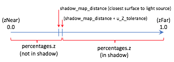
return percentages.z > shadow_map_distance + u_Z_tolerance
}
The following diagram shows the relationships between the values in the fragment shader.
A WebGL Shadow Map Program
Please experiment with the following WebGL program that implements shadow maps. The program will render correct shadows in some configurations and not others. Please attempt to manipulate the scene to create incorrect shadows and then discern why the errors are occurring.
Experiment with Shadows
Virtual World Shadows Rendering| camera eye (0.0, 0.0, 5.0) | camera center (0.0, 0.0, 0.0) |
| X: -5.0 +5.0 | X: -5.0 +5.0 |
| Y: -5.0 +5.0 | Y: -5.0 +5.0 |
| Z: -5.0 +5.0 | Z: -5.0 +5.0 |
Use orthographic projection
Use perspective projection
| perspective(fovy, aspect, near, far) | |||
| fovy: | 45 | 5.0 179.0 | |
| aspect: | 1.0 | 0.1 5.0 | |
| near : | 1.0 | 0.1 10.0 | |
| far : | 10.0 | 2.0 20.0 | |
| Light is on? (Rendered in red) | ||
| light 0 position(3.0, 0.0, 5.0) | light 0 color (1.00, 1.00, 1.00) | |
| X: -5.0 +5.0 | Red: | 0.0 1.0 |
| Y: -5.0 +5.0 | Green: | 0.0 1.0 |
| Z: -5.0 +5.0 | Blue: | 0.0 1.0 |
Use orthographic projection
Use perspective projection
| left: | -2.0 | -5.0 5.0 | right: | 2.0 | -5.0 5.0 |
| bottom: | -2.0 | -5.0 5.0 | top: | 2.0 | -5.0 5.0 |
| near: | 1.0 | -5.0 15.0 | far: | 10.0 | -5.0 15.0 |
| Light is on? (Rendered in green) | ||
| light 1 position(-3.0, 0.0, 5.0) | light 1 color (1.00, 1.00, 1.00) | |
| X: -5.0 +5.0 | Red: | 0.0 1.0 |
| Y: -5.0 +5.0 | Green: | 0.0 1.0 |
| Z: -5.0 +5.0 | Blue: | 0.0 1.0 |
Use orthographic projection
Use perspective projection
| left: | -2.0 | -5.0 5.0 | right: | 2.0 | -5.0 5.0 |
| bottom: | -2.0 | -5.0 5.0 | top: | 2.0 | -5.0 5.0 |
| near: | 1.0 | -5.0 15.0 | far: | 10.0 | -5.0 15.0 |
| ambient intensities (0.30, 0.30, 0.30) |
attenuation 1.0/(1.0 + 0.10*d + 0.00*d^2) |
||
| Red: | 0.0 1.0 | c1: | 0.0 3.0 |
| Green: | 0.0 1.0 | c2: | 0.0 3.0 |
| Blue: | 0.0 1.0 | Change all intensities at once. | |
| Render which model? |
Three planes. Cubes along axes. |
||
| shininess = 30.0 | |||
| 0.1 128.0 | |||
|
Display the shadow maps. (The darker the intensity, the closer the surface.) |
Shadow map for light 0 Shadow map for light 1 |
| Select the resolution of the shadow maps: |
64x64 128x128 256x256 512x512 1024x1024 |
| Tolerance for z depth comparisons +/-: 0.0000100 | 0.0 0.0000100 |
Dealing with Shadow Map Errors
Shadows will be rendered incorrectly by a shadow map algorithm for the following reasons:
The shadow map does not include surfaces that are visible from the camera.
If a fragment shader performs a
texture2Dlookup from a shadow map and the location is outside the texture map, the location is outside the projection of the shadow map rendering. The texture map was initialized to use the edge values in such cases (i.e.,gl.CLAMP_TO_EDGE) but this will almost certainly be wrong.Configure the WebGL program above to have visible surfaces that are not included in the shadow map. (Use the
centerpoint of the camera.) What happens to the shadows?Low resolution of the shadow maps.
Change the resolution of the shadow maps in the above WebGL program. What happens when the shadow maps are configured to be 64 by 64 pixels? Gradually increase the resolution and observe the results on the shadows. (You can also render the shadow maps into the right canvas.)
The z-value from the shadow map is not identical to the calculated z-value from the vantage point of the light source. This is due to three things: the mapping of the values to the depth buffer, floating point round-off errors and linear interpolation in a
texture2Dlookup. To account for the difference in the values a “tolerance factor” can be added to the value retrieved from a shadow map. However, a single tolerance value may not produce accurate results for all possible scenes.If a shadow map is created using an orthographic projection, the z-values in the depth buffer have a linear mapping. Therefore, the same tolerance value should perform reasonably well for most depth values in a scene.
If a shadow map is created using a perspective projection, the z-values in the depth buffer have a non-linear mapping. Therefore, the tolerance value must be adjusted based on the z-value retrieved from the shadow map. If the z-value is close to
0.0, the errors will be smaller than when the z-value is closer to1.0. Lesson 9.4 discusses the details of a perspective projection and the important details are repeated here.When you render a shadow map using a perspective projection, the following values are stored in the
gl_Positionoutput variable of the vertex shader.gl_Position[2] = c1 + (-z)*c2 // z component (distance from the camera) gl_Position[3] = -z; // w component (the perspective divide)
The
c1andc2constants are defined by the distance between the z clipping planes:c1 = 2*near*far / (near-far); c2 = (far+near) / (far-near);
The depth buffer has a specific number of bits allocated for storing the distance from the camera of each fragment. After the perspective divide, the
zvalues are in normalized device coordinates, which are floating point numbers between -1.0 and +1.0. To map these values to the depth buffer, the values are scaled by 0.5 and shifted by 0.5 to be between 0.0 and +1.0 and then converted to unsigned integers. The exact math is:depth_buffer[x][y] = ((z * 0.5) + 0.5) * (2^bits_per_value - 1);

Errors in shadow calculations.
Since the difference between adjacent depth values is different for every pair of values, the potential error is different as well. The graph to the right shows the errors for various values of z, where the near clipping plan is -4 and the far clipping plane is -50. Simply put, the tolerance for error must increase based on the magnitude of the depth value.
Summary
Rendering to a framebuffer that is defined using texture maps is a powerful idea that can be used to produce many other computer graphics effects besides shadows.
Shadow maps are only one of several algorithms that can render shadows. The Wikipedia article on shadow maps is a good reference for investigating other algorithms that can implement shadows.
Glossary
- shadow
- The portion of a surface that does not receive direct light from a light source.
- shadow map
- A texture map used to determine if a fragment receives direct light or is in a shadow.
- WebGL extension
- Functionality added to a WebGL API (application programmer interface).
- frame buffer
- A group of buffers used for rendering. It must contain a color buffer. If hidden surface removal is enabled it must also contain a depth duffer.
- depth_texture_extension
- A WebGL extension that allows a texture map to be used as the depth buffer of a frame buffer. This extension also adds the option to create a texture map that contains 32-bit unsigned integers for each value of the map.
Self Assessment
- ambient light
- Correct. Ambient light has no specific source. Therefore it can’t be blocked.
- diffuse light
- Incorrect. Diffuse light must strike the surface and reflect off.
- specular light
- Incorrect. Specular light must strike the surface and reflect off.
- attenuated light
- Incorrect. The attenuation of light is the decrease in a light’s intensity based on the distance between a light source and a surface.
Q-502: If light is blocked from hitting a surface, the surface should be colored using what type of lighting?
- the distance from a light source to the closest surface.
- Correct.
- a RGBA color of the closest surface to a light source.
- Incorrect.
- a boolean (true/false) value that indicates if a pixel is in a shadow.
- Incorrect.
- a floating point value in the range 0.0 to 1.0 that is a percentage of likelihood that a pixel is in a shadow.
- Incorrect.
Q-503: A shadow map contains what type of information?
- A
texture2Dlookup on a texture map can be performed by a fragment shader to retrieve a specific value. - Correct.
- A texture map is stored in the GPU’s memory and a fragment shader has very fast access to it.
- Correct.
- A texture map can be the depth buffer of a frame buffer.
- Correct.
- Texture maps store 2D arrays of RGBA colors.
- Incorrect.
Q-504: A shadow map is technically a texture map because … ? (Select all that apply.)
-
Match each "3d space" with the calculations that are performed in that space.
Please try again!
- model space
- no calculations
- camera space
- lighting
- normalize device coordinates
- clipping, perspective division, and viewport mapping
- light source space
- shadow map lookups
- “Scene camera“‘s center location.
- Correct.
- “Scene camera“‘s up vector.
- Correct.
- “Scene camera“‘s eye location.
- Incorrect.
Q-505: Setting up a “camera” to create a shadow map for a point light source is problematic because a camera has a line-of-sight, whereas a point light source shines light in all directions. This lesson suggests a strategy for creating a “light source camera”. Using this strategy, which of the following are shared between a “scene camera” and a “light source camera”. (Select all that apply.)
- Orthographic
- Correct. Because the mapping of z values to the depth buffer is linear.
- Perspective
- Incorrect. Because the mapping of z values to the depth buffer is non-linear.
Q-506: Distance values retrieved from a shadow map must be used with a “tolerance” value to compensate for losses in precision. Which type of projection has a fairly consistent error over the entire range of distance values?