12.7 - Rendering Points
In preparation for a discussion of “particle systems” in the next lesson, this lesson explains how to render points using WebGL.
Points
A point is a single location in 3D space defined by a (x,y,z)
value. By default, the rendering of a point sets the color of one pixel
in an image. The color of multiple pixels can be set by specifying the
gl_PointSize property of a point in a vertex shader.
gl_PointSize is the side length of a square centered at the point’s
raster location. It is a floating point value in pixel units.
The exact definition from the OpenGl ES 2.0 specification is:
gl_PointSize
Point rasterization produces a fragment for each framebuffer pixel whose center lies inside a square centered at the point’s (xw, yw), with side length equal to the point size.
If the point (xw, yw) is not directly in the center of a pixel and the
value of gl_PointSize is fractional, the area colored for a “point”
will be rectangular.
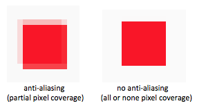
Anti-aliasing
Anti-aliasing is a technique for minimizing the errors due to sampling a 3D
scene only at the center of each pixel location. With no anti-aliasing,
a pixel is either colored, or not colored, depending on whether the center
of the pixel is inside a primitive’s boundaries. This produces
a jagged edge at the boundaries of a triangle, line, or point rendering.
When anti-aliasing is enabled, pixels receive a portion of the color of a primitive
based on a percentage of coverage of a pixel. The images below show a point
rendered with a gl_PointSize of 8.0 and enlarged to view individual pixels.
With anti-aliasing disabled, a point rendered with a size of 8.0 will color exactly
64 pixels. With anti-aliasing enabled, the edges around the 64 pixels will potentially
have partial coloring.
WebGL enables anti-aliasing by default. To disable it, the antialias
option must be set to false when the WebGL context is initially created.
The commands look something like this:
canvas = document.getElementById(canvas_id);
gl = canvas.getContext('webgl', {antialias : false} );
Anti-aliasing is rarely disabled. This discussion was primarily to help you understand why the borders of a multi-pixel “point” are typically lighter shades of the color assigned by a fragment shader.
Experiment with gl_PointSize
The following WebGL program renders eight points at the corners of a cube. Experiment with the program by varying the point size.
Experiment with gl_PointSize.
| Size = 2.0 | 1.0 100.0 |
(Use query: gl.getParameter(gl.ALIASED_POINT_SIZE_RANGE))
Animate
Experiments:
Disable anti-aliasing when the gl context is created. (See lines 107-108 in the
points1_scene.jsfile.) To see the difference between anti-aliasing and no anti-aliasing use any tool on your computer that allows the screen to be “zoomed in”.- On a Mac: Enable “Zoom” in the “Accessibility” tools of the “System Preferences”.
- On a PC: Use the “Magnifier” tool.
Enable anti-aliasing and change the point size while in a “zoomed” state to investigate the pixels at the boundaries of a point rendering.
Use the distance of a point from the camera to set its size. (Use the following code for the vertex shader.) Many variations on this idea are possible.
// Transform the location of the vertex.
gl_Position = u_Transform * vec4(a_Vertex, 1.0);

// Set the size of a rendered point.
gl_PointSize = u_Size - gl_Position.z;
(Please note that the
gl_Position.zvalue is the clipping-space z-component from a perspective projection which is a non-linear value. An accurate distance from the camera can be calculated using a camera-space transformation.)
Non-square Points
When points are rendered by a vertex shader, (and only for points),
the vertex shader passes an additional variable to the fragment shader,
gl_PointCoord, which is 2-component vector that gives the location
of a fragment relative to it’s “point” square. The components are in the range 0.0 to
1.0, where [0.0,0.0] is the upper-left corner of the square, [1.0, 1.0]
is the lower-right corner of the square, and [0.5,0.5] is the center of
the square.
A fragment shader can use the gl_PointCoord values to determine
how to manipulate a specific pixel. For example, it is straightforward to render
a “point” as a circle instead of a square. The GLSL distance
function can be used to calculate
the distance from a fragment’s location, gl_PointCoord, to the
center of the “point”, (0.5,0.5). If the distance is greater than 0.5, the fragment
is not inside a circle centered at the point’s location. Note that the GLSL statement,
discard, in a fragment shader prevents the graphics pipeline
from performing any further processing of a fragment.
Experiment with size of the points in the following WebGL program and study the fragment shader.
Experiment with gl_PointCoord.
| Size = 2.0 | 1.0 100.0 |
Experiments:
In the fragment shader, change the greater-than sign in the distance test to a less-than sign. (I.e.,
if (distance(center, gl_PointCoord) < 0.5).
Predict the results and then verify that you predicted correctly.Change the fragment shader to the single line:
gl_FragColor = vec4(gl_PointCoord, 0.0, 1.0);
Study the resulting output until it makes sense. (Note that the upper-left corner of each square is black, which means thatgl_PointCoordmust be(0,0)for the upper-left pixel.)Change the fragment shader to this logic:
float d = distance(center, gl_PointCoord);
if (mod(floor(d*4.0), 2.0) == 0.0) {
  discard;
}
gl_FragColor = u_Color;
Try various scalar values other than
4.0and see what happens.Change the fragment shader to this logic:
float d = distance(center, gl_PointCoord);
if (d >= 0.5) discard;
float alpha = 1.0 - d*2.0; /* center has the largest alpha */
gl_FragColor = vec4(u_Color.rgb, alpha);
(Note that the alpha component of the fragment’s color is changing from 1.0 at the center of the circle to 0.0 at the edges.)
Change the fragment shader to this logic:
float d = distance(center, gl_PointCoord);
if (gl_PointCoord.t > 0.5 || d >= 0.5) discard;
d = 1.0 - d*2.0;
gl_FragColor = vec4(u_Color.rgb, d);
(Note that the bottom half of the circle has been discarded.)
Come up with your own experiments. Your goal is to understand how to use
gl_PointCoordto manipulate the shape and color of a “point” rendering.
Billboard (or Sprite)
A billboard in computer graphics is a texture mapped quad
(four sided polygon) that always faces the camera, regardless of
its location and 3D orientation. A sprite is a 2D image that
can be rendered into a scene. The common practice in WebGL is
to render billboards and sprites as “points” with an appropriate
gl_PointSize and texture map image. Practical uses of these
techniques are presented in the lesson on “particle systems.”
To texture map a “point” there are two basic scenarios:
- The entire texture map image is mapped to the point’s square.
The implementation is straightforward –
use
gl_PointCoordas the texture coordinates for atexture2Dlookup. - A point has an associated texture coordinate that defines a location
in a texture map image for the center pixel of a point rendering.
Adjacent pixels of the texture map image are used to color adjacent
pixels in the point’s square. This requires the calculation of fractional
offsets within a texture map image to get to adjacent pixels and
the conversion of
gl_PointCoordinto pixel offsets.
The following two WebGL programs use this tileable image,  , as a texture map.
1) Map Entire Image to a “Point”
Experiment with billboards.
| Size = 30.0 | 1.0 100.0 |
| Translate X = 30.0 | -2.0 2.0 |
If you look closely, the texture map image is flipped on the
vertical axis. Why? Because the gl_PointCoord values
use the upper-left corner for (0,0), while texture coordinates
have their origin in the bottom-left of an image. The orientation
of the texture map can be flipped by inverting the .t
component like this:
vec2 coords = vec2(gl_PointCoord.s, 1.0 - gl_PointCoord.t);
gl_FragColor = texture2D(u_Texture_unit, coords);
Modify the fragment shader above to verify that this flips the texture map image to its original orientation.
Clipping Points
The clipping of points is not consistent across all browsers.
On Macintosh systems, clipping is based on the single (x,y,z)
location of the point. This can cause the rendering of a point
to “pop-in” and “pop-out” of a scene. If a billboard or sprite
needs to be partially clipped against a viewing volume, it
must be rendered using triangles.
On Windows and Linux systems, clipping is based on the entire square rendering of a point and any portion of a point’s square that is visible is rendered, even if the point itself is outside the clipping volume.
2) Map Adjacent Pixels to a “Point”
Texture coordinates are fractional percentages in the range 0.0 to 1.0. The fraction required to increment from one pixel to an adjacent pixel in a texture map image is based on the image’s dimensions. These increments can be calculated once and passed to a fragment shader:
texture_delta = [ (1.0 / (texture_map_image.width - 1.0)),
                  (1.0 / (texture_map_image.height - 1.0))];
gl.uniform2fv(program.u_Texture_delta, texture_delta);
(This technique was previously described in Lesson 11.10 on bump maps.)
To use the gl_PointCoord values to determine the relative
position of a fragment compared to the center pixel of the point’s square,
a fractional percentage is required, but based on the dimensions
of the point’s square. A point rendering is always square, so a single
fractional percentage is needed: 1.0/(point_size-1.0).
Therefore, take gl_PointCoord and move it to the center of the
square, divide it by the fractional percentage, and convert to an integer.
This provides a relative integer offset from the center pixel. The
correct adjacent pixel can now be retrieved from the texture map.
Please experiment with the following WebGL program and study the fragment shader. Notice that when the size of a point increases, extra pixels from the texture map are used to fill the new area. This is different from the previous WebGL program where the entire texture map was used for the point’s square.
Experiment with billboards.
| Size = 30.0 | 1.0 100.0 |
Summary
The previous two WebGL programs demonstrate billboards and sprites but not how they are typically used in practice. Rarely are billboards and sprites rendered as pure squares. By manipulating the alpha color value of individual pixels, a point’s square can become transparent in specific locations to render any shape desirable. Please try to combine some of the techniques described in the “Non-square Points” section with the billboards programs to investigate what is possible.
Glossary
- point
- A single location in 3D space.
- gl_PointSize
- A predefined output variable of a vertex shader when rendering points. It is the side length of a square, in pixels, that is centered about the location of a 3D point.
- gl_PointCoord
- A 2D vector where each component is a percentage value between 0.0 and 1.0.
It gives the relative location of a fragment compared to the square that
composes the entire point rendering.
[0,0]is the upper-left corner. - billboard
- A rendering of a texture map onto a quad surface that is always facing the camera.
- sprite
- The rendering of a 2D image into a 3D scene, where the image is always directly facing the camera.
Self Assessment
- 1
- Correct.
- 2
- Incorrect.
- 4
- Incorrect.
- 8
- Incorrect.
Q-507: The default rendering of a point (when gl_PointSize is not set) colors how many pixels?
- partially coloring adjacent pixels to the edge of a graphic primitive if an edge pixel is only partially covered by the edge.
- Correct.
- correcting aliasing, which is sampling error.
- (Kind of correct, but really meaningless jargon.)
- correcting errors.
- (What kind of errors? Too vague!)
- fixing the color of pixels at the center of a graphic primitive.
- Incorrect. Anti-aliasing works at the edges of a graphics primitive, not its center.
Q-508: Anti-aliasing is a technique for …
- The dimensions of a square, in pixels.
- Correct.
- The number of pixels to color when rendering a point, in pixels.
- Incorrect.
- The dimensions of a square, in world units.
-
Incorrect.
gl_PointSizeis not in world units. - The radius of a circle centered at a 3D location, in pixels.
- Incorrect.
Q-509: The vertex shader output variable, gl_PointSize, is a measure of what?
- [0.0, 1.0]
- Correct. They are percentages that give the location of a fragment within it’s point rendering.
- [0.0,
gl_PointSize] - Incorrect.
- [-1.0, 1.0]
- Incorrect.
- [
-gl_PointSize,gl_PointSize] - Incorrect.
Q-510: The fragment shader input variable, gl_PointCoord, is a vec2
whose components are in what range?
- [0.5, 0.5]
- Correct. This is the center of the point’s square.
- [0.0, 0.0]
- Incorrect. No, this is the upper-left corner pixel.
- [1.0, 1.0]
- Incorrect. No, this is the lower-right corner pixel.
- [0.75, 0.25]
- Incorrect. No, this pixel is to the right of center, and up from the center, of the point’s location.
Q-511: What is the value of the fragment shader input variable, gl_PointCoord, for
the pixel that is at the center of a point’s rendering? (I.e., the exact location of a
point?)
- None of the point’s square is rendered.
- Correct. A point’s square is rendered or not rendered based on whether a single 3D location is inside the projection’s clipping volume.
- The portion of the point’s square that is visible from the camera is rendered.
- Incorrect.
- The location of the point is modified in 3D space to guarantee its entire rendering.
- Incorrect. The graphics pipeline never modifies geometric primitive data.
- The alpha component of the point’s color is modified to make the point fade out.
- Incorrect. The graphics pipeline never modifies geometric primitive data.
Q-512: What happens to the rendering of a point if the 3D location of the point is not inside the projection’s clipping volume?
- Map an entire texture map to a point’s square.
- Correct. The fragment shader is a single line of code.
- Map a small sub-area of a texture map to a point’s square.
- Incorrect. Calculations must be performed to get offsets to adjacent pixels.
- Render a point as a circle and texture map it.
- Incorrect. Requires at least two lines of fragment shader code.
- Render a point as a “bulls eye”.
- Incorrect. Requires multiple lines of fragment shader code.
Q-513: Given the following options, which is simplest for a fragment shader to calculate?