11.10 - Bump / Normal Maps
The previous chapter explained how to model light. Both the diffuse and specular lighting calculations require a normal vector. In lesson 11.3 we discussed two scenarios for defining the normal vectors:
- Flat Shading - one normal vector for a triangle. The diffuse color for a triangle is identical for all of its fragments.
- Smooth Shading - each vertex has a separate normal vector. This vector is typically an average of the normal vectors from the adjacent triangles. Interpolating the vertex normal vectors across the surface produces a distinct normal vector for each fragment. However, the normal vectors change uniformly across the surface which causes the color to change uniformly across the surface.
Let’s investigate a third option: a distinct normal vector for every fragment of a triangle. Texture mapping allows the retrieval of a unique color for each fragment. Could texture mapping techniques be used to retrieve a unique normal vector for each fragment? YES! And there are two standard techniques:
- A bump map uses information from a texture map to modify a flat or smooth shaded normal vector.
- A normal map uses a texture map to retrieve a distinct normal vector.
Changing the normal vector for each fragment changes the percentage of diffuse and specular light that is reflected, thus allowing for the simulation of surface variations on a triangle’s face.
Bump Maps
Bump maps can be image-based or procedural-based. In the case of images,
the image is assumed to be a greyscale image that contains a single intensity
value per pixel. In the case of procedural texture maps, a single percentage value
is calculated in the range [0.0,1.0].
The details to implement bump mapping are non-trivial, so let’s start with the big idea:
- Each vertex of a triangle has a normal vector. The vertex shader puts
the normal vector into a
varyingvariable and each fragment gets an interpolated normal vector. - The fragment shader uses a texture map to get a
<deltaX,deltaY>offset to modify its normal vector. This “tweak” in the normal vector must be applied relative to the triangle’s orientation. Therefore, each triangle must be able to calculate or retrieve a local coordinate system. ThedeltaXoffset must be applied in a direction that is “to the right” relative to the triangle’s surface. Similarly, thedeltaYoffset must be applied in a direction that is “upward” relative to the triangle’s surface. - The diffuse and specular lighting calculations are performed using the new normal vector.
There are two major tasks in step 2: produce a (deltaX,deltaY) offset
from a texture map and use a triangle’s local coordinate system to modify
a fragment’s normal vector.
Getting the Normal Vector Offsets
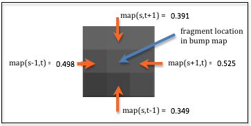
For a texture map implemented using a “bump map image”
a (deltaX,deltaY) offset can be calculated from the four
surrounding pixels of the fragment’s location in the bump map image.
The amount of relative change around the image location can be calculated
using the difference between values in the horizontal and vertical directions.
(In mathematics this is called a “finite difference.”) The diagram
to the right shows nine pixels in an enlarged area of an image where the difference
between the horizontal pixels is 0.027, i.e., (0.525 - 0.498), and the difference
between the vertical pixels is 0.042, i.e., (0.391 - 0.349). This gives a offset
to modify the surface normal vector that is proportional to the changes
in the bump map image. In the diagram’s example the offset vector is <0.027, 0.042>.
In a fragment shader the normal vector offsets can be calculated using the following
example code. To retrieve adjacent pixels, the amount of change in
the texture coordinates can be calculated by dividing the image dimensions into 1.0.
For example, if the image has a width of 512 pixels, 1.0/512.0, (i.e., 0.001953125) needs
to added to a u texture coordinate to get to its adjacent pixel.
1 2 3 4 5 6 7 8 9 10 11 12 13 14 15 16 17 18 19 20 21 22 | // The dimensions of the bump map image: (width, height)
uniform vec2 u_Image_size;
//-------------------------------------------------------------------------
// Given texture coordinates, calculate the "finite difference"
// between neighboring pixels.
vec2 get_bump_offsets(vec2 texture_coordinates) {
float pixel_delta_u = 1.0 / u_Image_size[0];
float pixel_delta_v = 1.0 / u_Image_size[1];
vec2 up = vec2(0.0, pixel_delta_v);
vec2 down = vec2(0.0, -pixel_delta_v);
vec2 left = vec2(-pixel_delta_u, 0.0);
vec2 right = vec2( pixel_delta_u, 0.0);
vec4 right_color = texture2D(u_Texture_unit, texture_coordinates + right);
vec4 left_color = texture2D(u_Texture_unit, texture_coordinates + left);
vec4 up_color = texture2D(u_Texture_unit, texture_coordinates + up);
vec4 down_color = texture2D(u_Texture_unit, texture_coordinates + down);
return vec2(right_color[0] - left_color[0], up_color[0] - down_color[0]);
}
|
Modifying a Normal Vector
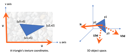
Just as a model has a local coordinate system, every triangle in a model has its own local coordinate system. The normal vector of a triangle vertex points away from the triangle’s front face. Let’s assume the normal vector is equivalent to the Z axis of the triangle’s local coordinate system, and the equivalent X and Y axes lie in the plane defined by the triangle’s surface. We can solve for the vectors that represent the X and Y axes such that they have an equivalent orientation to the axes of the texture map.
In the diagram below, the left diagram shows a triangle in “texture coordinate
space.” Regardless of the actual dimensions of the texture map image,
the U and the V axes have unit length and the texture coordinates
(u1,v1), (u2,v2), and (u3,v3) are percentages in the
range [0.0,1.0]. The normal vector for the triangle is coming out of
the diagram towards you. In the right diagram is a 3D plot of the same triangle.
The vectors U3d and V3d can be calculated such that they lie
in the plane defined by the triangle and they are consistent with the
orientation of the texture map. Said another way, we want to calculate where
U and V would be in 3D space if the texture map was placed
on the surface of the 3D triangle.
Vector Math
All vectors are defined with reference to a coordinate system. For example,
<3,4> is a vector that changes 3 units along the X axis and 4 units
along the Y axis. The vector can be represented as the sum of two vectors,
3*<1,0> + 4*<0,1>. The axis vectors, <1,0> and <0,1>,
are the “basis” for the definition.
Any vector can be represented by the sum of two scaled “basis” vectors.
In the “3D space” diagram above, the vectors <p3-p1> and p2-p1
can be represented using the vectors U3d and V3d as their “basis”.
The “lengths” applied to the “basis” vectors comes from the corresponding
vectors in the “texture coordinates space”. This provides the following two
equations:
1 2 | <p2-p1> = (u2-u1)*U3d + (v2-v1)*V3d
<p3-p1> = (u3-u1)*U3d + (v3-v1)*V3d
|
These can be solved for the “basis” vectors, U3d and V3d to give:
1 2 | U3d = ((v3-v1)<p2-p1> - (v2-v1)<p3-p1>) / ((u2-u1)(v3-v1) - (v2-v1)(u3-u1))
V3d = ((u3-u1)<p2-p1> - (u2-u1)<p3-p1>) / ((v2-v1)(u3-u1) - (u2-u1)(v3-v1))
|
These vectors have the correct directions to define a 3D local coordinate system but their lengths are not one. Therefore the vectors need to be normalized:
1 2 | v_U3d = normalize(v_U3d);
v_V3d = normalize(v_V3d);
|
Using these vectors, the offsets from the bump map image can be applied to
a normal vector. The “x offset” travels along the U3d axis and the
“y offset” travels along the V3d axis. The new normal vector
is calculated like this:
1 | new_normal = normal + x_offset * U3d + y_offset * V3d;
|
This new_normal must be normalized because the lighting
calculations expect a normal vector of unit length.
In summary, the offsets retrieved from the bump map image are applied to the normal vector relative to the triangle’s local coordinate system. To calculate the local coordinate system all of the vertices of the triangle and all of the texture coordinates of the triangle must be accessible. There are two scenarios:
- If a model’s geometry and texture coordinates never change,
pre-calculate the
U3dandV3dvectors and store them in a GPU buffer object on a per vertex basis. This requires memory for 6 extra floats per vertex. - If a model’s geometry or texture coordinates are modified during rendering,
the
U3dandV3dvectors must be calculated in the vertex shader or the fragment shader during rendering. This requires that extra GPU buffer objects be created to store the other two vertices and the other two texture coordinates for the current triangle vertex. This requires 10 extra floats per vertex.
Caveat
It should be noted that the vectors N, U3d and V3d are
typically not orthogonal and do not define a precise coordinate system (which
requires that coordinate axes be 90 degrees apart). However, this is OK because
we never use the three vectors to form an actual coordinate system.
An Example WebGL Program
The following WebGL program stores two extra vertices and two extra texture coordinates
for each vertex and calculates a “local coordinate system” for each
triangle vertex in the vertex shader. The U3d and V3d vectors
are placed into varying variables so they are available to the fragment shader.
Please experiment with the program and study the shader program. Please note
that all of the lighting calculations are performed in “camera space” and therefore
the U3d and V3d vectors must be converted to “camera space” as well
(lines 76-77 in th vertex shader).
Make sure you investigate the difference between using an image as the source for surface colors vs. modifying the surface normals. You can change the WebGL program rendering below under the “Model Properties” options.
Experiment with a Bump Map
Virtual World Bump mapped cube| camera eye (0.0, 0.0, 5.0) | camera center (0.0, 0.0, 0.0) |
| X: -5.0 +5.0 | X: -5.0 +5.0 |
| Y: -5.0 +5.0 | Y: -5.0 +5.0 |
| Z: -5.0 +5.0 | Z: -5.0 +5.0 |
| light position(3.0, 0.0, 5.0) | light color (1.00, 1.00, 1.00) | |
| X: -5.0 +5.0 | Red: | 0.0 1.0 |
| Y: -5.0 +5.0 | Green: | 0.0 1.0 |
| Z: -5.0 +5.0 | Blue: | 0.0 1.0 |
| ambient intensities (0.30, 0.30, 0.30) |
|
| Red: | 0.0 1.0 |
| Green: | 0.0 1.0 |
| Blue: | 0.0 1.0 |
| Change all intensities at once. | |
| shininess = 30.0 | |||
| 0.1 128.0 | |||
|
Use the bump map image to modify the normal vectors. Use the bump map image for the surface color. |
|||
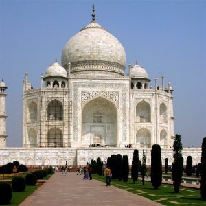
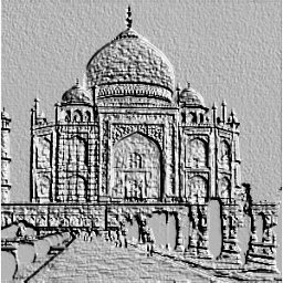
Using Gimp to Create Bump Maps
Gimp includes tools for creating bump maps. One such tool is the emboss tool (Filters –> Distorts –> Emboss). The tool only works on color images. The WebGL program above uses an example image from Gimp’s documentation. The original color image is shown below, along with the results of changing the image size to a power of 2 and applying the embossing tool.
| Original color image | “Embossed” image |
|---|---|
|
|
Do a web search for “creating bump maps using Gimp” to learn further techniques and details on bump map creation.
Normal Maps
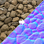
An image and its
associated normal map (1)
A normal map is a variation on bump maps. The RGB values in a normal map image
are not used to modify a normal vector - they are the normal vector!
An RGB pixel value, (red,green,blue), is used as a <dx,dy,dz>
normal vector. The normal map is defined in the X-Y plane with the +Z axis being
the general direction of the surface normal. Since the color (0,0,1) is blue,
normal map images tend to be “blueish” in color, as in the example image to the right.
Normal vectors can point in any direction, but image color components are always
positive values in the range [0.0, 1.0]. Therefore, normal vectors have to
be transformed before they can be stored in an image. Given a normal vector component
value in the range [-1.0, 1.0], it is scale by 1/2 and then offset by
1/2 to get it in the range [0.0, 1.0] (e.g, component*0.5 + 0.5). When
a color is extracted from the image, each component must be converted
back into a normal vector value by undoing the transformation, i.e.,
component*2.0 - 1.0.
Transforming Normal Vectors into “Triangle Space”
As with bump maps, normal map vectors must be transformed so they are relative
to the surface they are modeling. Using the equations developed above for bump maps,
the vectors U3d and V3d, along with a vertex’s normal vector N,
can be used to create a local coordinate system for that vertex. A coordinate
system is defined by 3 orthogonal vectors, so the three vectors must be made
orthogonal. This can be done by taking the cross-product of two of the vectors
to calculate the third vector. The order that you perform the cross-products
determines the exact orientation of the coordinate system. Here are two possible
scenarios:
- Assume the normal vector should be orthogonal to the triangle’s surface:
- The vectors
U3dandV3dline on the triangle’s surface, socross(U3d, V3d)calculatesN. - Since
Nwas calculated using a cross-product, it must be orthogonal to bothU3dandV3d. Therefore, the only other operation required is to getU3dandV3dorthogonal. This can be done using eitherV3d = cross(N, U3d)orU3d = cross(V3d, N).
- The vectors
- Assume the normal vector is for smooth shading and that it is not
orthogonal to the triangle’s surface:
Nshould not be changed, so recalculate bothU3dandV3dto make them orthogonal.V3d = cross(N, U3d)U3d = cross(V3d, N)
We now have a valid coordinate system defined by the vectors U3d,
V3d, and N. In lesson 7.6 you learned that a transformation
matrix to position and orient a model in 3D space can be easily created from the
model’s local coordinate system. The vectors that define the coordinate system
are the columns of the transformation matrix:
uy
uz
0
vx
vy
vz
0
nx
ny
nz
0
0
0
0
1
Eq1
Since we are transforming vectors which have direction but no location, the 4th row and column are not needed. Therefore, the following matrix will transform a vector defined in “global 3D space” into a triangle’s local coordinate space:
U3dy
U3dz
V3dx
V3dy
V3dz
Nx
Ny
Nz
Eq2
In GLSL, a mat3 data type defines a 3-by-3 matrix defined in column-major
order. Therefore, a transformation matrix can be created easily with this statement:
v_Local_coordinate_system = mat3(U3d, V3d, N);
Normal Maps in a Fragment Shader
The following fragment shader statements perform the required normal map calculations. Notice that the vector is retrieved from the normal map image, transformed into the orientation of the current 3D triangle, and then transformed into camera space for lighting calculations.
1 2 3 4 5 6 7 8 9 10 11 12 13 14 15 16 17 18 19 20 | // Get the normal vector from the "normal map"
normal = vec3(texture2D(u_Texture_unit, v_Texture_coordinate));
// Transform the component values from [0.0,1.0] to [-1.0,+1.0]
normal = normal * 2.0 - 1.0;
// Transform the normal vector based on the triangle's
// local coordinate system
normal = v_Local_coordinate_system * normal;
// Transform the normal vector into camera space for the
// lighting calculations.
normal = vec3(u_To_camera_space * vec4(normal, 0.0) );
// Perform the lighting calculations.
color = light_calculations(vec3(v_Color), normal,
u_Light_position, u_Light_color);
// Add in the ambient light
color = color + u_Ambient_intensities * vec3(v_Color);
|
A WebGL Normal Map Program
Please experiment with the following program and study the shader programs.
Experiment with a Normal Map
Virtual World Normal mapped cube| camera eye (0.0, 0.0, 5.0) | camera center (0.0, 0.0, 0.0) |
| X: -5.0 +5.0 | X: -5.0 +5.0 |
| Y: -5.0 +5.0 | Y: -5.0 +5.0 |
| Z: -5.0 +5.0 | Z: -5.0 +5.0 |
| light position(3.0, 0.0, 5.0) | light color (1.00, 1.00, 1.00) | |
| X: -5.0 +5.0 | Red: | 0.0 1.0 |
| Y: -5.0 +5.0 | Green: | 0.0 1.0 |
| Z: -5.0 +5.0 | Blue: | 0.0 1.0 |
| ambient intensities (0.30, 0.30, 0.30) |
|
| Red: | 0.0 1.0 |
| Green: | 0.0 1.0 |
| Blue: | 0.0 1.0 |
| Change all intensities at once. | |
| shininess = 30.0 | |||
| 0.1 128.0 | |||
|
Use the normal map image to set the normal vectors. Use the normal map image for the surface color. |
|||
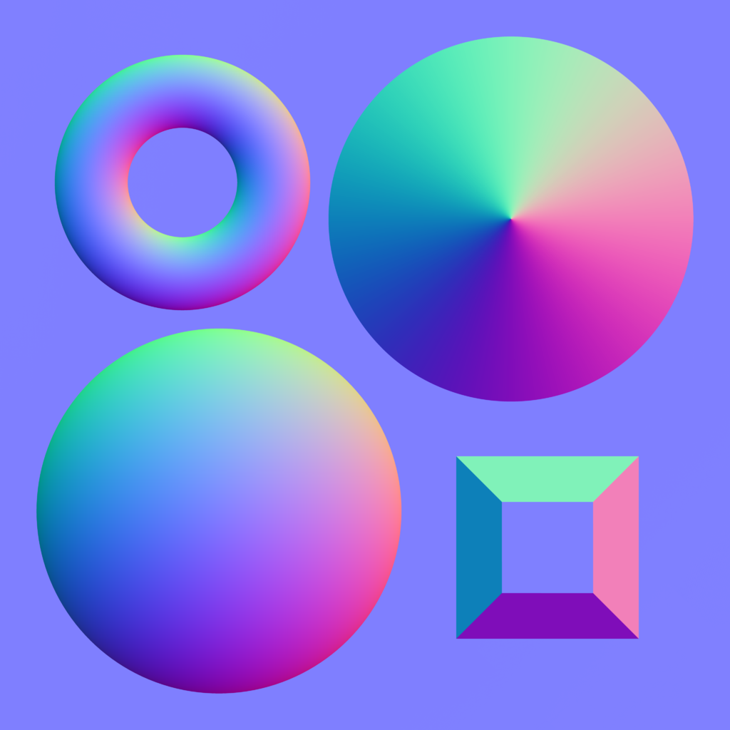
An example normal map (here)
Creating Normal Maps
The normal map used in the WebGL program above is shown to the right. It was created by Julian Herzog and is available from “creative commons” here.
Special tools and processes are required to create normal map images. Using Blender, the workflow is:
- Model a highly detailed (“hi-poly”) model
- Bake the Bump and/or Normal maps
- Make a low-poly, less detailed model
- Map the map to the low-poly model using a common coordinate system
To “bake” a normal map (or other 3D modeling data) simply means to save the data to a file for later use.
Gimp can be used to create normal maps from images, but as of version 2.8.16 it requires the installation of special plug-ins.
More Advanced Techniques
After mastering bump maps and normal maps you might investigate parallax mapping which is an enhancement that modifies the texture coordinates at a fragment to provide greater realism and more illusion of depth.
Glossary
- mapping
- Given inputs, return an output.
- bump map
- Use a value from an image to shift the direction of a fragment’s normal vector, which modifies the amount of light it reflects.
- normal map
- Use a RGB value from an image as the normal vector for a fragment.
Self Assessment
-
Match each type of surface property modeling with its correct definition.
Please try again!
- bump map
- "Finite differences" in an image are used to modify a fragment's normal vector.
- normal map
- Colors from an image are used as a fragment's normal vector.
- heightmap
- Colors from an image are used as "height" values for vertices.
- displacement map
- Colors from an image are used as displacements along a vertex's normal vector.
- both the vertex shader and the fragment shader
- Correct. The vertex shader retrieves (or calculates) a local coordinate system for a triangle; The fragment shader retrieves (or calculates) a normal vector for a fragment.
- vertex shader
- Incorrect. (But part of the work is done in the vertex shader.)
- fragment shader
- Incorrect. (But part of the work is done in the fragment shader.)
- JavaScript pre-processing code.
- Incorrect.
Q-462: Where are bump maps and normal maps implemented?
- add the fraction
1.0/Image_sizeto a texture coordinate value. - Correct.
- add 0.01 to a texture coordinate value.
- Incorrect.
- add 1.0 to a texture coordinate value.
- Incorrect.
- using the color of the current pixel, add 1.0 to the color.
- Incorrect.
Q-463: How do you retrieve an adjacent pixel in a texture map image?
- Creating a bump map image is easily done using tools in Gimp.
- Correct.
- Creating a normal map image is easily done using tools in Gimp.
- Incorrect. Creating a normal map requires special tools or Gimp plug-ins.
- Higher intensity pixels in a gray-scale bump map image represent taller bumps.
- Correct.
- A normal map image requires RGB color values, not gray-scale values.
- Correct. The color values are the normal vectors.
Q-464: Which of the following are true? (Select all that apply.)