11.11 - Combining Surface Properties
This has been a long chapter and perhaps you have forgot what it is even about! So let’s review for a moment.
A 3D model is represented by a triangular mesh. To simulate real-world objects the surface properties of the triangles must be modeled. In this chapter we have discussed how to model surface properties using the following techniques:
- Modeling the diffuse, specular, and ambient color of a surface.
- Simulating a curved surface by varying the normal vectors of vertices (smooth shading).
- Mapping colors from an image onto a surface (image texture mapping).
- Mapping colors from a procedural calculation onto a surface (procedural texture mapping).
- Transformations on texture coordinates to modify (or animate) a surface pattern.
- Modifying the actual geometry of a surface using heightmaps or displacement maps.
- Modifying how light reflects from a surface using bump maps or normal maps.
We have examined each of these techniques in isolation, but the rendering of a model is typically performed by a combination of many (or all) of these techniques. This lesson discusses implementation issues related to combining these techniques in shader programs.
Software Development Issues
Good software development habits are invaluable when developing complex shader programs. Make it your habit to do the following:
- Procedural Decomposition - break a problem down into simpler sub-problems. Implement each sub-problem as a distinct procedure.
- Incremental Development - develop and debug distinct procedures independent from the overall problem.
- Systematic Integration - create a solution to the overall problem by systematically adding in pieces to the overall solution.
- Data vs. Algorithm - a rendering can be incorrect due to bad data, a bad algorithm, or the incorrect coding of an algorithm. Always make sure you have good data before attempting to debug your algorithms.
The output of a shader program is a 2D image. As you are testing and debugging
a shader program put the values you are trying to debug into the gl_FragColor
output variable. Specific examples of how to do this are described below.
Tasks for Creating a WebGL program
The following WebGL program renders a “bunny” by combining smooth shading, image texture mapping, bump maps, and an ambient, diffuse, and specular lighting model. Before experimenting with the demo program, please review the following tasks that were required to create this program:
The model of a “bunny” was downloaded from the internet: http://graphics.stanford.edu/data/3Dscanrep/
Using Blender:
The model was defined in a
.plydata file. It was imported into Blender and exported as an.objdata file.The original polygonal mesh had 35,947 vertices and 69,451 triangles. To reduce the size of the mesh, the
X(delete memu) –>Limited dissolvecommand was used. This created multi-sided polygons that were changed into triangles usingCRTL f(face menu) –>Triangulate Faces. The model was reduced to 22,271 vertices and 42,128 triangles. TheCRTL v(vertices) –>Smooth Vertextool was also used to smooth out the location of the vertices.Triangular mesh errors were fixed. For example, some of the triangles had their normal vectors pointing inward (instead of outward). In addition, every face was given the “smooth face” property to enable smooth shading.
A material was created and assigned to all of the model faces.
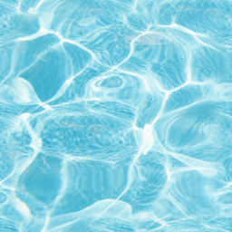
A texture map was created to color all the faces: water.png
A texture map was created to bump map the faces: leather-bump-map.jpg
Texture coordinates were created for all the faces using the “unwrap” command. However, they were very poor texture coordinates.
The original model had 4 “holes” in the bottom of the model which made the assignment of texture coordinates problematic. Most of the triangles on the bottom of the model were deleted to create one large hole. The “unwrap” command then produced more reasonable texture coordinates.
The model was exported to an
.objfile with only vertices and texture coordinates. This makes the file as small as possible. (The functionCreateModelsFromOBJ()will calculate normal vectors after the file has been downloaded from a server.)The triangles that formed the bunny’s eyes were manipulated to create a cleaner, more circular model for each eye.
The texture coordinates for the triangles that form the bunny’s eyes were move to the upper-right corner of the texture map image. Gimp was used to color a black rectangle in this part of the texture map image. Therefore, the bunny’s eyes are colored black.
The assignment of texture coordinates took the most work. The image below shows the layout of the texture coordinates for the entire model.
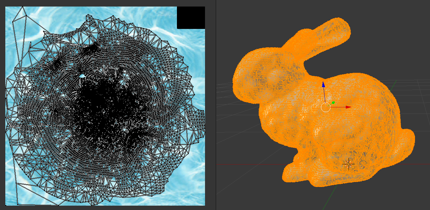
All texture coordinates
In the image below, only the texture coordinates for the head and ears are shown highlighted in orange. The head and ears received very little “texturing” while most the pattern in the
water.pngimage is being applied to the body of the bunny. This makes for a nice rendering, but an infinite number of other texture coordinates assignments are possible.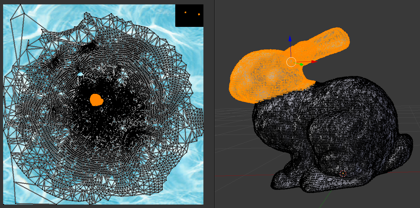
Only the head texture coordinates
The “unwrap” command created texture coordinates for parts of the bunny’s ears that were so condensed they were equal to each other. This caused the local coordinate system of these triangles to calculate zero length vectors, which caused the bump map calculations to produce an invalid normal vector, which created a black color for these triangles. In Blender the texture coordinates for these triangles were moved to a different part of the bump map image and scaled to larger values, but still values that mapped to a single pixel. This fixed the problem with the bump map calculations and kept the ears predominately the same color.
Gimp was used to resize the the bump map image to a power of 2 and the
Colors–>Brightness-Contrasttool was used to darken the image, which made the “bumps” smaller. The original image and its final version are shown below.Original image Final “bump map” image 

The shader program was created in several stages, adding successive layers of complexity one at a time.
This brief overview of the work required to create the WebGL program below is typical of the issues you will face when you create new WebGL programs. Your tasks and issues may vary widely based on your models and your desired final output.
A WebGL Program
Experiment with the following program and study its shader program. The bump map used is very subtle. Please manipulate the bump map transformation parameters to visually see the “bumps”. After investigating the program, please perform the experiments listed below the demo program.
Experiment with Multiple Surface Properties
Virtual World A Bunny| camera eye (0.0, 0.0, 5.0) | camera center (0.0, 0.5, 0.0) |
| X: -5.0 +5.0 | X: -5.0 +5.0 |
| Y: -5.0 +5.0 | Y: -5.0 +5.0 |
| Z: -5.0 +5.0 | Z: -5.0 +5.0 |
| light position(3.0, 0.0, 5.0) | light color (1.00, 1.00, 1.00) | |
| X: -5.0 +5.0 | Red: | 0.0 1.0 |
| Y: -5.0 +5.0 | Green: | 0.0 1.0 |
| Z: -5.0 +5.0 | Blue: | 0.0 1.0 |
| ambient intensities (0.30, 0.30, 0.30) |
|
| Red: | 0.0 1.0 |
| Green: | 0.0 1.0 |
| Blue: | 0.0 1.0 |
| Change all intensities at once. | |
| shininess = 30.0 | |||
| 0.1 128.0 |
| tx = 0.00 | -4.0 4.0 |
| ty = 0.00 | -4.0 4.0 |
| sx = 0.00 | -4.0 4.0 |
| sy = 0.00 | -4.0 4.0 |
| Scale both axes | |
| angle = 0 | -360.0 +360.0 |
Debugging Shader Programs
Please make the following changes to the shader program above and study the results. These exercises will help you understand how to debug shader programs.
Look at the vertices by changing line 151 in the fragment shader from
gl_FragColor = vec4(color, 1.0);togl_FragColor = vec4(v_Vertex, 1.0);. You should see smooth colors across the model’s surfaces. (Remember that color values are always positive, so you can scale and offset the vertices to get more details in the dark areas usinggl_FragColor = vec4(v_Vertex * 0.5 + 0.5, 1.0);
Study the normal vectors:
gl_FragColor = vec4(v_Normal, 1.0);Study the texture coordinates:
gl_FragColor = vec4(v_Texture_coordinate, 0.0, 1.0);. Note that the areas where you see a “solid color” are areas where the texture coordinates are not changing very much and were a single pixel color from the texture map image will be used over large areas.Study the texture mapped colors:
gl_FragColor = frag_color;Examine the diffuse color calculation. Since the diffuse color is calculated inside a procedure, create a temporary global variable at the top of the fragment shader (add
vec3 temp;). In thelight_calculationsfunction, around line 103, calculate the diffuse color using white for the surface color,temp = vec3(1.0, 1.0, 1.0) * light_color * cos_angle;. Change the last line in the fragment shader togl_FragColor = vec4(temp, 1.0);.Suppose there is a problem with calculating the local coordinate system for each triangle. Examine the value of the vectors
v_U3dandv_V3d. (Usegl_FragColor = vec4(v_U3d, 1.0);.)Further investigating the local coordinate system for each triangle, determine if any of the coordinate system axes are degenerate vectors that have zero length. The code might look like this:
if (length(v_U3d) == 0.0) {
  color = vec3(1.0, 0.0, 0.0);
} else {
  color = vec3(0.0, 1.0, 0.0);
}
gl_FragColor = vec4(color, 1.0);
If you see any red in the rendering, those are locations in the triangular mesh that have an invalid local coordinate system.
GPU’s have floating point errors just like CPU’s. For example, study the output of this code:
if (length(normalize(v_Normal)) == 1.0) {
  color = vec3(1.0, 0.0, 0.0);
} else {
  color = vec3(0.0, 1.0, 0.0);
}
gl_FragColor = vec4(color, 1.0);
The output shows a random set of red and green pixels. This is because the length of a vector is often not exactly 1.0. It might be 0.999999 or 1.000001. Try this code:
if (length(normalize(v_Normal)) >= 0.999) {
  color = vec3(1.0, 0.0, 0.0);
} else {
  color = vec3(0.0, 1.0, 0.0);
}
gl_FragColor = vec4(color, 1.0);
The model should now be all red. When working with floating point values in shader programs, take into account round-off errors as necessary.
Come up with you own experiments. Be creative!
Summary
Creating beautiful renderings requires significant work. Hopefully this lesson has helped you understand some of the processes required and some of the issues you might encounter. With experience, the work becomes easier and less confusing.
Beautiful renderings typically require a combination of modeling techniques. The number of possible combinations is very large!
Self Assessment
If you performed all of the above experiments and understood the resulting output, then you have already completed a good self-assessment. If the experiments were confusing, please try them again!