10.1 - Introduction to Lighting
Your eyes “see” an object because light has reflected from the object into your eye. Without light, nothing is visible. This lesson introduces the basic properties of reflected light and how we can simulate light in a virtual scene.
This is a major shift in this textbook. Up to this time we have been discussing the manipulation of the geometry of virtual models and how to compose a scene. All of this work has been accomplished by transformation matrices that do their work in a vertex shader program. Now we need to discuss how to create the visual appearance of model surfaces. The majority of this work will be done in a fragment shader program.
Please Review Light Properties
Please re-read lesson 3.6 - Modeling Light Sources.
Pause
Did you re-read lesson 3.6. If not, please read it now. It’s important!
Modeling a Light Source
There are many different sources of light. Four commonly used models to describe light sources are:
- Point light source:
The light is inside the scene at a specific location and it shines light equally in all directions (e.g., a table lamp). Point light sources are modeled using a single location,(x,y,z,1).
- Sun light source:
The light is outside the scene and far enough away that all rays of light have the same direction. An example is the sun in an outdoor scene. Sun light sources are modeled as a single vector,<dx, dy, dz, 0>, which defines the direction of the light rays.
- Spotlight light source:
The light is focused and forms a cone-shaped envelop as it projects out from the light source. An example is a spotlight in a theatre. Spotlights are modeled as a location,(x,y,z,1), a direction,<dx.dy,dz,0>, a cone angle, and an exponent that defines the density of light inside the spotlight cone.
- Area light source:
The light source comes from a rectangular area and projects light from one side of the rectangle. An example is a florescent light fixture in a ceiling panel. Area light sources are modeled using a location,(x,y,z,1), a geometric model, such as a rectangle, (4 vertices), and a direction,<dx.dy,dz,0>.
All of these models have one common attribute: the direction of light rays from a light source. In the following lessons we will discuss how the direction of light is used to calculate the color of individual pixels on a surface.
Color of Light
Light from a table lamp or the sun it typically a shade of white. However,
some sources of light are not white, such as a red stop
light or a blue neon sign. When we
model a light source, we specify its color using an RGB color
value. If a light source gives off white light, we model its color
as (1.0, 1.0, 1.0). If the light source gives off red light, we model its
color as (1.0, 0.0, 0.0). Each color component is a percentage: 0.0
means no color; 1.0 means 100% color. Note that white light, (1,1,1),
is composed of 100% red, 100% blue, and 100% green light.
If a white light shines on an object, and you see the object as red, then the red component of the reflected light has reached your eyes. Note that the green and blue components of the light were absorbed by the object’s surface. A red object absorbs all wavelengths of light except the red wavelengths. This means that if a blue light reflects from a red surface, you see black! All of the blue light was absorbed by the surface and there was no red light to reflect. Our lighting models will implement this basic characteristic of light.
Calculating Light Reflection
To calculate light reflections, which will be done in a shader program executed by a GPU, a shader program must know the position and orientation of three things:
- the object being rendered, whose geometry is stored in a GPU vertex object buffer,
- the camera, whose definition is in a transformation matrix, and
- the light sources, whose definition will be passed to a shader program as
uniformsbecause a light source does not change for a specific rendering.
All example WebGL programs in this textbook, up to this point, have used a single transformation matrix to position, orient, and scale objects in a scene. However, now that we want to do lighting calculations, we need to re-think the use of a single transformation matrix. Consider the three fundamental transformations done on the vertices of a model, which are shown in the diagram below.
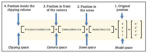
Possible “spaces” for lighting calculations
If we break a transformation into its distinct parts, we have four possible geometric spaces in which to perform lighting calculations:
- The original position: (model space)
This is the original definition of the object. It does not represent the object’s position or orientation for a particular scene. Therefore these values can’t be used for lighting calculations.
- Position in the scene: (scene space)
This is the position and orientation of an object after being transformed by the model transform. This places the object’s location and orientation relative to the other objects in the scene. Assuming that we know the location and orientation of the light sources and the camera, we could perform accurate light reflection calculations using these values.
- Position in front of the camera: (camera space)
This is the position and orientation of an object after being moved in front of a stationary camera located at the global origin. This retains the relative location and orientation of objects in a scene. Assuming that we know the location and orientation of the light sources, we can perform light reflection calculations using these values. Notice that for these geometric values, the camera is located at the origin with its local coordinate system aligned to the global coordinate system. This has the advantage that we don’t have to send the camera’s location and orientation to the shader programs because we know exactly where the camera is.
- Position inside the clipping volume: (clipping space)
The geometric values have been transformed by the projection transform and are ready for clipping. The meaning of thexandyvalues have been de-coupled from thezvalues of each geometric vertex. The vertices no longer have their same relative relationship with other 3D positions in the scene. (Remember, a perspective transform does a non-linear mapping of the z values into the clipping volume.) Therefore, these values can’t be used for lighting calculations.
Therefore, we have two possible “3D spaces” in which to perform lighting calculations. The “camera space” has a clear advantage because the camera is in a known location and orientation and we don’t have to transfer its position and orientation to the GPU shader programs. In addition, the camera is located at the global origin which simplifies some of the light reflection calculations.
To perform lighting calculations in shader programs we will create two distinct transformation matrices in our JavaScript program and pass both of them to the shader programs. This transformation matrix:
*CameraMatrix
*ModelMatrix
*x
y
z
w
=x'
y'
z'
w'
Eq1
will perform all of the transformations required for the graphics pipeline, while the following transformation matrix will produce locations and orientations for lighting calculations.
*ModelMatrix
*x
y
z
w
=x'
y'
z'
w'
Eq2
Obviously you should avoid unnecessary calculations, which means the camera and model transformations should not be multiplied twice, so your Javascript code should look something like this:
// Create the lighting transformation.
matrix.multiply(camera_space, camera, model);

// Create the pipeline transformation.
matrix.multiply(clip_space, projection, camera_space);
Lighting Algorithm
To simulate light in a scene, the following steps need to be performed:
- In your JavaScript program:
- Create a camera space transformation matrix. (CameraMatrix times ModelMatrix)
- Multiply the light model’s data times the camera space transformation matrix to put the light source into its correct position and orientation in camera space.
- Transfer the light model’s data to the GPU’s shader programs
- Create an second transformation matrix that includes the desired
projection matrix. (We will call this the
clip_spacetransformation matrix.) - Transfer the
camera_spaceand theclip_spacetransformation matrices to the GPU’s shader programs.
- In your GPU shader program:
- Assume the camera is at the global origin looking down the -Z axis.
- Use the light source data and the model data to calculate light reflection.
- Assign a color to a pixel based on the light reflection.
Lesson Organization
The following lessons on lighting describe how to implement point light sources and follow this general outline:
- Introduce a “lighting model.”
- Explain the math needed to calculate the “lighting model.”
- Describe the key features of a WebGL program that implements the “lighting model”. It is very important that you experiment with the WebGL program to understand the visual effects of the “lighting model”.
- Explain the details of the shader programs that implement the “lighting model.”
If you understand how to implement lighting for point light sources, you should be able to extend these ideas to other types of lights, such as sun, spotlights, and area lights.
The details can be overwhelming, so please take your time and master each lighting model before moving on to the next, more complex lighting model.
Glossary
- light source
- Where light in a scene comes from.
- light model
- A set of data and algorithms that simulates a light source and how it interacts with objects in a scene.
- model space
- A geometric definition of a model using its local coordinate system. Models are defined in relationship to the global origin, which simplifies their transformation into a scene.
- scene space
- A geometric definition of a model after it has been positioned and oriented in a scene.
- camera space
- A geometric definition of a model after it has been positioned and oriented in a scene and moved in front of a camera.
- clipping space
- A geometric definition of a model after it has been transformed into normalize device coordinates, also known as the clipping volume.
Self Assessment
- A set of data and algorithms that simulates a light source and how it interacts with objects in a scene.
- Correct.
- A geometric representation of a lamp.
- Incorrect. You might create such an object for a scene, but lighting models are only concerned with the light from its bulb.
- A model that does not weigh much.
- Incorrect. That’s silly!
- An equation that explains light ray reflections from a surface.
- Incorrect. But this might be a part of a light model.
Q-205: What is a “light model”?
- A point light source shines light in all directions.
- Correct.
- A point light source has an implied direction due to its location.
- Incorrect.
- A point light source is not inside the scene, and therefore its direction of light does not matter.
- Incorrect.
- A point light source can’t send light in specific directions.
- Incorrect. It actually sends light in all directions.
Q-206: Why does a “point light source” not need a “direction” for modeling light (like the other lighting models)?
- Point light source
- Incorrect. Point light sources shine light in all directions.
- Sun light source
- Correct. All light rays from the sun have the same direction because the sun is so far away from the scene.
- Spotlight light source
- Correct. The direction the spotlight is pointed is critical.
- Area light source
- Correct. Area light sources only shine light to one side of the defined area.
Q-207: Which types of light sources require a direction for the light? (Select all that apply.)
- black
- Correct. All of the red light is absorbed by the green object and there is no green light to reflect.
- red
- Incorrect. Nope!
- green
- Incorrect. You might think a green object is always green, but the light illuminating it matters!
- blue
- Incorrect. Say what?
Q-208: If a flashlight emits red light and you shine it on a green object, what color will your eye see?
- camera space
-
Correct. The camera is at the origin looking down the -Z axis, so we don’t have to
transfer the camera data to the fragment shader and some to the lighting calculations
are simplified because the camera is at
(0,0,0,1). - model space
- Incorrect. The relationships between the models, camera, and lights has not been established for the scene.
- scene space
- Incorrect. Lighting calculations can be done in scene space, but the location and orientation of the camera must be copied to the fragment shader and some of the lighting calculations are more complex.
- clipping space
- Incorrect. The relationships between the models, camera, and lights is wrong because of the conversion to normalized device coordinates.
Q-209: In what geometric space will lighting calculations be perform in this textbook?
- Two, one to put geometry into camera space, and another to put geometry into clipping space.
- Correct.
- Only the
projection
*camera
*model
transform. - Incorrect. This puts geometry into clipping space and we need geometry in camera space to calculate lighting.
- Three: the projection, camera, and model transformations.
- Incorrect. If you pass these matrices as separate transformations, the vertex shader will have to multiply them together every time it processes a vertex, which will cause duplication of work and greatly slow down rendering.
- Only one, the projection matrix.
- Incorrect. The project matrix, by itself, is not very useful.
Q-210: How many transformation matrices will a vertex shader need when rendering a model?