9.5 - Viewports
A projection transformation has prepared your models for clipping, which discards any primitive elements (points, lines or triangles) that are outside the camera’s field-of-view. Clipping is performed automatically by the graphics pipeline after your vertex shader has been executed on every vertex in a scene. The graphics pipeline has also automatically performed the “perspective division” on all vertices in the scene. Now, its time to create an image!
This lesson describes how a scene’s geometric data is mapped to a 2D image.
The Viewport Transformation

Your geometric data is defined by (x,y,z) values that are inside a
2x2x2 clipping volume centered at the origin. Its time for
the pipeline to start creating a 2D image. The image will be mapped
into a HTML canvas element, so the image is created to be the same size (in pixels)
as the canvas element . A WebGL image uses a coordinate system that has
an origin in the lower-left corner,
with the +X axis going to the right and the +Y axis going up, as shown in
the image to the right. The vertex data from the clipping volume needs
to be mapped into image locations. This is done with two simple transformations:
- Scale the
(-1,-1)to(+1,+1)viewing window to the image’s width and height. - Translate the lower-left corner at
(-width/2,-height/2)to the image’s origin,(0,0).
In matrix format, this transformation is
*scale
*x
y
z
1
=xImage
yImage
zDepth
1
Eq1
0
0
0
0
1
0
0
0
0
1
0
width/2
height/2
0
1
*width/2
0
0
0
0
height/2
0
0
0
0
1
0
0
0
0
1
*x
y
z
1
=xImage
yImage
zDepth
1
Eq2
Notice that we are only transforming the x and y coordinated of each vertex because we are creating a 2D image. The z component is carried along with the vertex, but its value remains unchanged.
You don’t implement the viewport transformation. It is done internally by the graphics pipeline. The default behaviour is to cover the entire canvas with the rendering. However, you can modify the viewport with this command:
gl.viewport(x_offset, y_offset, view_width, view_height);
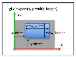
Viewport Parameters
The x_offset and y_offset parameters specify the offset from the
lower left corner and the view_width and view_height parameters
specify the size of the rendered image, in pixels. When taking into account that
the viewport may not cover the entire canvas,
the viewport transformation is:
*translate_to_window
*scale
*x
y
z
1
=xImage
yImage
zDepth
1
Eq3
0
0
0
0
1
0
0
0
0
1
0
x_offset
y_offset
0
1
*1
0
0
0
0
1
0
0
0
0
1
0
view_width/2
view_width/2
0
1
*view_width/2
0
0
0
0
view_width/2
0
0
0
0
1
0
0
0
0
1
*x
y
z
1
=xImage
yImage
zDepth
1
Eq4
The following WebGL program allows you to experiment with the viewport command.
Experiment with a viewport.
Show the viewport boundary
Manipulate the parameters of gl.viewport(xoffset, yoffset, width, height)
| x_offset : | 0 | -100 300 |
| y_offset : | 0 | -100 300 |
| width : | 150 | 0 400 |
| height : | 150 | 0 400 |
As you experiment with the viewport parameters, please verify that you understand the following ideas:
- The viewport parameters determine the location and size of the rendered image
inside the canvas element. The default is to cover the entire canvas:
gl.viewport(0,0,canvas_width, canvas_height);. - The
offsetscan be negative and thewidthandheightcan be larger than the size of the target canvas. In these cases, part of the rendered image will not be visible. - If the
widthandheightcreate a viewport that has a different aspect ratio than the original canvas window, the rendering is distorted. - The
viewportcommand does not perform clipping! Clipping was performed in a previous stage of the graphics pipeline. Theviewportdetermines the size of the output image and the location of the image inside the target canvas element. - If your desire is multiple distinct renderings inside a single canvas, you need to use a concept called “scissoring,” which is described in the next lesson.
Mouse Events into World Locations
Sometimes you need to convert the location of a mouse cursor into a location in your 3D virtual scene. Since you are viewing a 3D world, a mouse location actually identifies an infinite number of points that lie on a ray from the camera through the mouse’s location into the 3D world. You can convert a mouse location into a viewing window location using simple proportions. Study the two diagrams below.

The screen coordinates used by a mouse have the +Y axis going down the screen,
but this does not matter if you use the same distances for your proportions.
In both diagrams we measure distances from the left side and the top side.
We use the variables left, right, bottom and top
that were used to define our projection matrices to describe the world
viewing window. Let’s use canvas_width and canvas_height to describe
the size of the canvas window. The relative distances in both windows must be
equal. Therefore:
x_mouse / canvas_width  === (x_world - left) / (right - left)
y_mouse / canvas_height === (top - y_world)  / (top - bottom)
If you know a mouse location, (x_mouse, y_mouse), you can solve the
above equations to calculate the equivalent location in the virtual world
on the viewing window. That is:
x_world = (x_mouse / canvas_width) * (right - left) + left;
y_world = top - (y_mouse / canvas_height) * (top - bottom);
If you want to convert a 3D location in the viewing window to a mouse location, the calculations are:
x_mouse = ((x_world - left) / (right - left)) * canvas_width;
y_mouse = ((top - y_world)  / (top - bottom)) * canvas_height;
The following WebGL program allows you to experiment with mouse coordinates converted to world coordinates.
Tracking the mouse in 3D.
|
Move your mouse in the canvas below and its location is displayed in the viewing window in the left rendering. The orange ray shows all of the 3D locations that are behind the mouse location. |
| Mouse Coordinates | World Coordinates | World Ray |
| (0,0) | (0,0,0) | ray = (0,0,0)*t, t>=1 |
Open this webgl demo program in a new tab or window
As you experiment with the mouse tracking demo, please verify that you understand the following ideas:
- The mouse location is a 2D position within a canvas element. We can project that location into a 3D world, either to a single point on the viewing window or as a ray that is cast into the 3D world. The ray is defined by two points: the location of the camera and the location of the 3D point.
Glossary
- viewport
- The portion of an HTML canvas you want to render into. The default viewport is the entire canvas.