1.3 - The 3D Graphics Pipeline
3D computer graphics takes a vector graphics representation of objects and creates a 2D raster image. But how? It is a non-trivial process that requires multiple steps involving almost every major component of a computing device. Let’s first review the major components of a computing device and then see how they are used to create computer graphic images.
Computational Device Hardware
Computer graphics is created by modern computing devices such as desktop computers, laptops, tablets, and cell phones. These devices are complex systems with many components. All devices that produce visual output to a screen will have the following types of processing units.
- CPU’s (central processing units) are the “brains” of a device. CPU’s perform the general processing and run the operating system (OS) which controls the overall functioning of the device.
- GPU’s (graphics processing units) are specially designed to render 3D graphics. However, in recent years they have also been used for other applications, such as speech recognition and neural network training. Any processing that requires large amounts of identical simultaneous computations can potentially be accelerated using a GPU.
Modern computing devices also contain many types of memory, each designed for specific purposes.
- RAM (random access memory) stores program data and program instructions.
- Graphics memory stores vector data, raster images, and a screen’s pixels. This memory has special properties that facilitates 3D graphics.
Here is a simplified diagram that shows the relationship between these components.
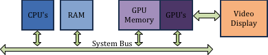
Major hardware pieces in a computing device
To create computer graphics imagery, all of these hardware components are used extensively.
Rendering using a “Graphics Pipeline”
The process of converting vector graphic representations of objects into a raster image is performed by a well defined, step-by-step process called the graphics pipeline. In the early days of computer graphics the pipeline was not programmable. Data was fed into the pipeline and out came a raster image on the other side. But today’s GPU’s allow for a programmer to control certain parts of the pipeline using shader programs. A shader program is a specialized set of instructions for manipulating graphics data in the graphics pipeline. Shader programs provide a programmer with amazing flexibility and potential creativity, but at the cost of added complexity.
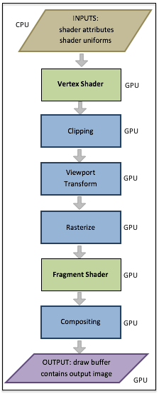
The Graphics Pipeline
Step 1 in the pipeline is data setup. A webGL program must establish a link between the attribute variables in a vertex shader program and the GPU buffers that hold the data those variables use. Any other data that the shaders need for a model rendering is also copied to the shader program. These are called uniform variables because they don’t change as a single rendering is performed.
Step 2 is execution of a vertex shader program on each vertex of a geometric primitive defined in model world coordinates. Each vertex is transformed into normalized device coordinates. This is typically done with a single matrix transformation matrix, which is a combination of transformations that move a model to the correct place in a scene, then positions the model in front of a virtual camera, and then projects the world coordinates into a unit cube.
Step 3 clips away all of the data that is outside the field-of-view of the virtual camera.
Step 4 maps the model data from normalized device coordinates into a viewport defined in pixels.
Step 5 rasterizes a geometric primitive by determining which pixels in the raster image are inside it’s boundaries.
Step 6 executes a fragment shader on each pixel that composes a geometric primitive and outputs a color value for the pixel.
Step 7 combines (composites) the color of a pixel from a fragment shader with the color of the pixel already assigned to the output draw buffer.
Note that step 1 is performed by the CPU from instructions specified in JavaScript code, while the remainder of the pipeline is performed by the GPU from shader program instructions defined in GLSL (OpenGL Shading Language). Step 1 uses data from RAM to setup a model render, while the GPU uses its own memory for the rest of the steps. Explaining the details of each of these pipeline steps is the purpose of this textbook.
Glossary
- CPU
- a central processing unit that controls a computing device and performs general calculations
- GPU
- a graphics processing unit is a hardware device that computes calculations and performs tasks specifically for a graphics pipeline.
- graphics pipeline
- a series of steps that perform a rendering process.
- shader program
- a computer program that runs on a GPU that performs one or more steps of a graphics pipeline.
- vertex shader
- a computer program that runs on a GPU to position the geometry of models in a scene.
- fragment shader
- a computer program that runs on a GPU to assign a color to the pixels that compose a surface of a model.
Assessments
-
Q-11: A graphics pipeline is …
- a well defined, step by step rendering process.
- Correct.
- a cable (i.e., pipe) that carries graphical signals inside a computer.
- No.
- a specific type of vector data.
- No.
- a way to communicate raster data.
- No.
        Q-13: Q-12: Please correctly order the following steps to the graphics pipeline.Setup geometric and scene data for the pipeline.
Execute a vertex shader on each vertex of a geometric model.
Clip away everything that is not in the camera's field-of-view.
Map the 3D object coordinates into pixel coordinates of a raster image.
Determine which specific pixels represent a geometric primitive.
Execute a fragment shader on each pixel that represents a geometric primitive.
Combine pixel colors.
Output a raster image.