9.1 - Introduction to Projections
When you render a 3-dimensional computer graphics scene, you create a 2-dimensional picture of the 3D scene. The picture is a projection of the models in the scene onto a 2-dimensional “screen”. Therefore it is logical to call this operation a projection.
There are two standard projections used in computer graphics. An orthographic projection maintains parallel lines but provides no sense of depth. A perspective projection provides for a sense of depth, but parallel lines are skewed toward vanishing points. Orthographic projections are used in the engineering fields when an accurate representation of a model is desired. Perspective projections are used when a “real life” view of a scene is desired because they simulate how the human eye sees the real world. Please study the following two examples and compare their outputs. You can rotate the view in both windows with a mouse click and drag.
Orthographic projection
|
Notice that:
|
Perspective projection
|
Notice that:
|
Projection Tasks
A WebGL projection must “project” a 3D scene onto a 2D image AND prepare the scene’s data for three important follow-on steps in the graphics pipeline, which are:
- Clipping - the removal of elements that are not in the camera’s line-of-sight.
- Viewport mapping - convert a camera’s viewing window into the pixels of an image.
- Perspective divide - performing a division on every vertex component to
implement a perspective projection (e.g.,
(x/w, y/w, z/w)).
These tasks are automatically performed by the graphics pipeline, but for these tasks to be implemented efficiently in the GPU, the scene’s data must be converted to a standard format called Normalized Device Coordinates, which is our next discussion.
Clipping

When you point a real camera at something to take a picture, only a portion of the real-world is visible in the camera’s field-of-view. The same is true of the human eye; you only see what is in front of you. We want the same behavior for our virtual scenes. The process of determining what is visible and what is not visible is called clipping. Clipping is done automatically by WegGL. However, to make clipping as efficient as possible, clipping is always done inside a cube centered at the origin.
The clipping volume is a 2 unit wide cube, with the X axis going from -1 to +1, the Y axis going from -1 to +1, and the Z axis going from -1 to +1, as shown in the image to the right. A scene that has been transformed to fit inside this clipping volume is said to be defined in Normalized Device Coordinates (NDC).
Did you notice that the clipping volume is defined in a left-handed coordinate system? The Z-axis is pointing into the page! Previous lessons have stated that WebGL always uses a right-handed coordinate system and now it doesn’t. What is going on? The designers of WebGL (i.e., OpenGL) believed that the “right-hand rule” for spacial orientation feels natural and comfortable for the majority of people, while the designers of graphics hardware wanted consistency of data. It is easy to reconcile these differences: for WebGL programs a projection is designed to invert the orientation of the coordinate system in preparation for GPU implemented functionality.
You can visually see the left-handed coordinate system of the GPU in the following demo program. Observe what happens when you include an projection matrix and when you don’t.
Render 3 triangles with or without a projection matrix.
|
Open this webgl demo program in a new tab or window
Given that the clipping volume uses a left-handed coordinate system, there are two very important implications to the WebGL graphics programmer:
- You must always include a projection matrix in your vertex transform, even if you don’t think you need one. All of the transformations we have defined previously assumed a right-handed coordinate system. If you don’t include a projection matrix, all of the other transformation matrices will not work correctly.
- If you create your own projection matrix, it must negate the z values of all vertices.
Clipping Algorithms
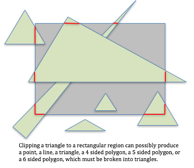
Clipping is a very difficult problem, as demonstrated by the image below. Clipping is one of the main reasons why WebGL only render points, lines and triangles. Clipping geometric primitives that are more complex than triangles is difficult and computationally expensive.
To better understand why clipping is done in normalized device coordinates,
consider how clipping points might be done using programming logic. To determine
if a point defined as (x,y,z) is inside the clipping volume, you might write
code like this:
if (x >= -1 and x <= 1 and
    y >= -1 and y <= 1 and
    z >= -1 and z <= 1)
  point_is_visible = true;
else
  point_is_visible = false;
However, since the clipping volume is uniform and symmetrical about the origin, using an absolute value function simplifies this code to:
if (abs(x) <= 1 and abs(y) <= 1 and abs(z) <= 1)
     point_is_visible = true;
else
     point_is_visible = false;
Furthermore, you could set the boolean value with just a simple assignment like this:
point_is_visible = (abs(x) <= 1 and abs(y) <= 1 and abs(z) <= 1);
Actually clipping is done in homogeneous coordinates (which you will learn more
about in a couple of lessons). For a (x,y,z,w) vertex, the clipping test would
be
point_is_visible = (abs(x/w) <= 1 and abs(y/w) <= 1 and abs(z/w) <= 1)

// Or, remove the division for efficiency to get
point_is_visible = (abs(x) <= w and abs(y) <= w and abs(z) <= w)
Summary
A projection must map a virtual scene into normalized device coordinates to facilitate efficient clipping.
You should be very grateful that the graphics pipeline implements clipping for you because it is a complex problem to solve.
Viewport Mapping
After clipping, the (x,y) values of vertices must be mapped to pixel
locations in a 2D image. Later in this chapter we will discuss the details of
this viewport mapping.
Perspective Divide
Creating a perspective view of a virtual scene requires a division operation on
each x, y, z, component of a vertex. This is accomplished by performing performing
transformations in 4D space and using the w component of each vertex for
a divisor. Later in this chapter we will discuss the details of the perspective divide
operation.
When Does a Projection Need To Happen?
A projection transformation must happen after a scene has been moved in front of a virtual camera, but before clipping occurs. A projection operation is performed by a 4-by-4 matrix multiplication, so it is typically pre-multiplied times the camera (or view) transform – which is pre-multiplied times the model transform(s).
=ProjectionMatrix
*ViewMatrix
*ModelMatrix
Eq1
In your JavaScript code you will typically create a single transformation matrix for a model and pass it to your vertex shader when you render the model. The remaining lessons in this chapter describe how to build a 4-by-4 projection matrix.
Glossary
- projection
- Transform the vertices of a 3D model into 2D points on a 2D viewing window. And prepare the 3D data for the next stages of the graphics pipeline.
- viewing window
- A rectangular 2D region on which a 3D world is projected.
- orthogonal projection
- Project all vertices of a scene along straight lines parallel to the Z axis.
- perspective projection
- Project all vertices of a scene along vectors to the camera’s location. Where the vector hits the 2D viewing window becomes it’s rendered location.
- clipping
- The process of determining what is visible and not visible in a virtual camera’s field of view.
- Normalized Device Coordinates (NDC)
- The 3D coordinate system that all scenes are converted into before clipping is performed.
Self Assessment
-
Q-199: What are the standard projection transformations?
- orthogonal
- Correct.
- perspective
- Correct.
- viewing window
- Incorrect. The viewing window is a plane on which the 3D world is projected.
- Normalized Device Coordinates
- Incorrect. The vertices of a scene are transformed into this range of values.
-
Q-200: Which projection maintains parallel lines and the size of models?
- orthogonal
- Correct.
- perspective
- Incorrect.
-
Q-201: Which projection creates a rendering that is similar to the view a human sees in the real world?
- perspective
- Correct.
- orthogonal
- Incorrect.
-
Q-202: A projection transformation “projects” a 3D world onto a 2D image AND performs which
of the following other tasks? (Select all that apply.)
- prepares the data for clipping.
- Correct.
- normalizes the data for viewport mapping.
- Correct.
- performs clipping.
- Incorrect. The projection transformation does not perform clipping. It simply gets the data ready for clipping.
- projects an image onto a screen.
- Incorrect. A physical "projector" shines an image onto a screen, but a projection transformation manipulates vertices.
-
Q-203: Clipping a triangle against the viewing window can result in what types of geometric primitives? (Select all that apply.)
- a triangle.
- Correct.
- a quad. (A 4-sided polygon.)
- Correct.
- a 5-sided polygon.
- Correct.
- a 6-sided polygon.
- Correct.
-
VertexTransform =ProjectionMatrix
*ViewMatrix
*ModelMatrix
- Correct. The projection must be the last operation performed on the vertices.
-
VertexTransform =ViewMatrix
*ProjectionMatrix
*ModelMatrix
- Incorrect. The camera must be applied to the scene before the projection.
-
VertexTransform =ModelMatrix
*ViewMatrix
*ProjectionMatrix
- Incorrect. This makes the projection transformation the first operation when it must be the last.
-
VertexTransform =ViewMatrix
*ModelMatrix
*ProjectionMatrix
- Incorrect. This makes the camera transformation the last operation, which is wrong.
Q-204: Which of the following matrix multiplications is the correct order for creating a single transformation matrix that can be used for a vertex shader?